Measuring cylinder ports for matching components, building engines or tuning cylinders… this information is crucial. But how different could the varying methods be? With 12 years measuring an array of cylinders we put Darrell to the task.
The two-stroke cylinder contains various ducts and passageways referred to as ports. These ports have a range of specifications in terms of height, width, corner radius, area, floor/roof and side angles. All of these play a role in the design of the cylinder, more so than people generally realise. For the purpose of this exercise, the focus is on just two types of port, the exhaust port and the adjacent transfer ports. This is to show the effects of measuring an exhaust port that sits high in the bore which has clearer visual access than a lower transfer port which is difficult to see and considerably smaller in size.
Donor engine
Our model was a unit with an aftermarket 62mm stroke crankshaft with a 120mm con rod, and a stock TS1225 cylinder, not a good match without remedial porting work but fine for the exercise planned. The first job was for us to set up the cylinder on the case to obtain a zero piston height at top dead centre, so the outer edge of the piston crown sits flush with the cylinder’s top face. To test this we used a head gasket of 0.92mm and 1mm soft-core solder.
We adjusted the base packer and torqued the cylinder/head down until we got 0.92mm squish on the solder. The reason for setting zero piston height is so that when measuring the ports from top of cylinder, we can use the figures ‘as measured’ and will not need to add or subtract any other clearances.
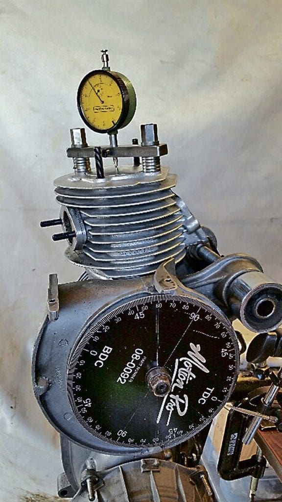
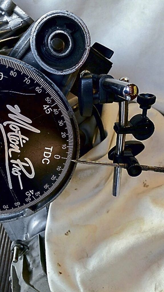
Next we fitted a degree wheel and a dial gauge set up. The degree wheel simply bolted onto the end of crank and tightened loosely for now with a washer either side followed by the flywheel nut. For the pointer a scribe was positioned in a magnetic mount and adjustable arm arrangement making a very secure pointer for our TDC marker. A second wire pointer was set up as a separate adjustable marker. The dial gauge was mounted in a holder that bolts between the cylinder studs with the head removed. It provides a good TDC indicator that we can use to set the degree wheel up with and go back to between tests to check it as a datum. The degree wheel on the crank end was rotated until the dial gauge indicator on the cylinder top was on its needle rocking point, then we adjusted up the dial gauge outer ring to read zero. The degree wheel was rotated on the crank to get it close to its 0/TDC mark before final tightening, followed by the scribe pointer being moved to align with the degree wheel’s TDC. Then clockwise and anti-clockwise checks were done to check all readings aligned at zero, and then we took our port measurements.
Measurement methods
Method 1: Degree wheel check from TDC down to port opening.
This requires just one visual reference on the port, plus a start (TDC) and finish (port opening) on the degree wheel and pointer. The exhaust port is the difficult one, especially as it can often have two measurement points: the top edge of the chamfer and then actual duct roof. On some bores a very mild chamfer means the roof will set the duration but a heavy chamfer will mean that sets the duration, and it can be seen from the light shining through from the outside. The same measurement is done with the transfer port, but being positioned lower in the bore it is more difficult to see the point the transfer opens.
Another consideration is that the casting of the port roofs may not been level, so I made a central marker pen line to work from. The final results were showing the exhaust port opening at 86.5° after TDC and transfers at 112° after TDC. The difference between the two (25.5°) is the blowdown figure (the duration exhaust port allows gases to escape before the delivery of fresh fuel/air mix at transfer opening). These are single direction measurements we now need to get a full port duration figure: so the exhaust port figure of 86.5 is doubled (173) and then removed from the 360° total. This gave the final result of 187° exhaust duration, and the same calcs for the transfers gave 136°.
Method 2: Visual degree wheel check from port open to port close.
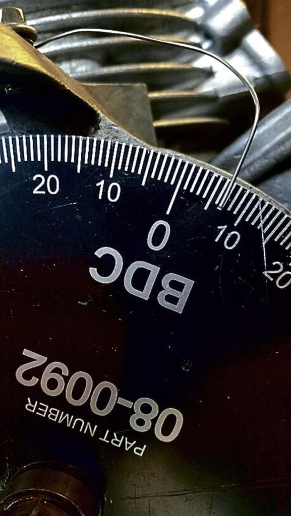
This is similar method 1, except instead of measuring above the ports and calculating, we simply use the degree wheel to measure the port directly. So we position the wire indicator on the degree wheel at our zero degrees start point from exhaust port opening and then swing down through BDC (bottom dead centre) and back up to exhaust port closing. That’s it! This allows the numbers read from the degree wheel as actual results without doing any further calcs. This method differs slightly in that it requires two visual references on the port, instead of a preset TDC as a start point like test 1, and so could introduce slight variation. The results came out as 186.5 exhaust and 135.5 transfer leaving us a same as test 1 25.5° blowdown.
Method 3: Feeler gauge degree wheel check from port open to port close.
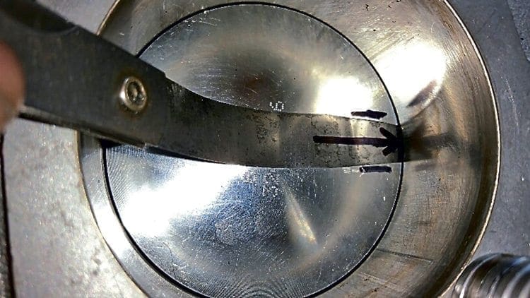
This is a similar to test 2 but instead of relying on a visual check of port open/close, we work with a feeler gauge that the piston will trap on the port roof, which is where the position indicator marks on the bore we made before will provide improved accuracy. The feeler gauge required careful selection from three sets at our disposal, the narrowest width ones were picked and we found a 0.4mm feeler gauge gave just enough flex to form in the middle of the port roof but not so thin that it collapsed.
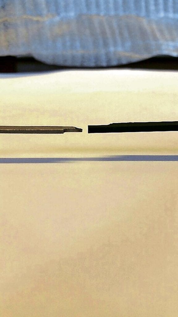
Its insertion depth was also marked off for repeatability and the holding method held on the piston crown centre read more accurately than closer to the outer edge or the opposite side. The figures produced using this method will require the 0.4mm worth of degrees adding to them. But what is 0.4mm in degrees? Be careful here because it’s not one fixed figure; it will vary with crank position. This is also what happens when you lift up or lower the cylinder with gaskets, the durations change by differing amounts!
The initial results came out as 185 exhaust and 135.5 transfer but require the 0.4mm feeler gauge thickness of degrees adding twice as the feeler was used to start from and finish, so in this case 0.8mm of change on exhaust is 2.93° and on the transfers a larger 3.51° giving us a final figure of 187.93 exhaust and 139.01 of transfer leaving us a 24.46° blowdown.
Method 4: Old school port map
This method is all change and often used when a cylinder is in your hand or fresh out of a box. Away with the cylinder dial-gauges/degree-wheels etc. and onto a method most people know as a ‘port rubbing’ or ‘port map’. This is where a paper template is placed in the bore and a rubbing taken with a pencil or similar then measurements are taken from the template and the durations calculated.
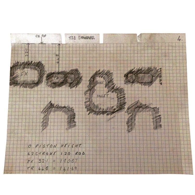
Traditionally these have always been my least favourite as without any information of how the top gasket face works in relation to the piston the map can end up being miles out. As a slight guide in this situation you could measure down from the drawn top face to the base of the transfers and exhaust and if designed for a 58mm stroke and it measures 58mm, then there’s a good chance it will be a 0 piston height. But most cylinders are cast differently and have different concepts so this doesn’t always apply. Without a piston height quoted it’s of little use.
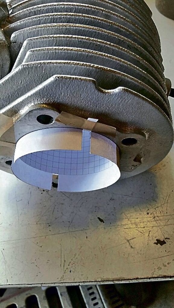
For the port map I selected a graph paper, this one has 5mm squares and a border all round it. I cut the border off on three sides but left the top border in place as I felt it would come in useful in a few ways. To start, instead of worrying about making it fit exactly length and width, I just rolled it as is and slid it in the bore. Using the graph lines it was easy to align the roll end both horizontally and vertically, and pushing the roll out tight into the bore I then attached a few small strips of tape.
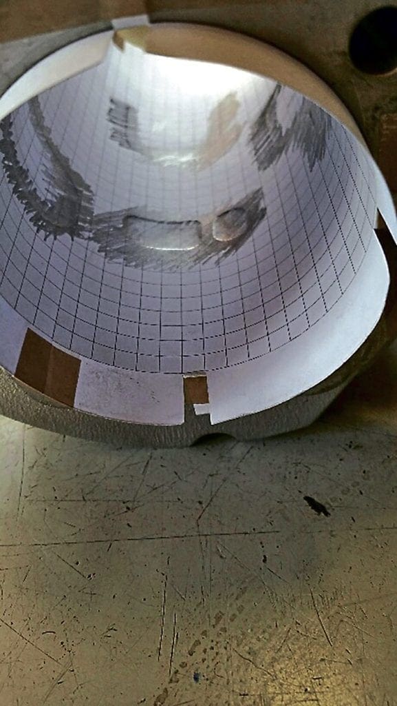
It was held in place nicely so that when the cylinder was held up to the light you could see the light shine through at the top border of the paper I’d left on, so a light tap down had the top line of the graph paper in alignment with the top gasket face. I then decided to cut out some 5mm wide strips in the border and fold them over, again to that top graph line, which left these strips available to tape down to stop the paper rotating during the pencil rubbing. It worked a treat and produced a clearly defined line to all ports.
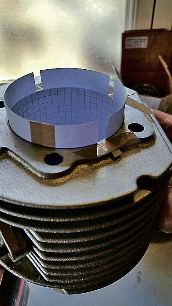
The results produced port heights for exhaust as 32.1mm and for transfer 44.8mm these give 190.87° exhaust and 141.69° of transfer leaving us a blowdown of 24.59°.
Method 5: Digital Vernier to degrees
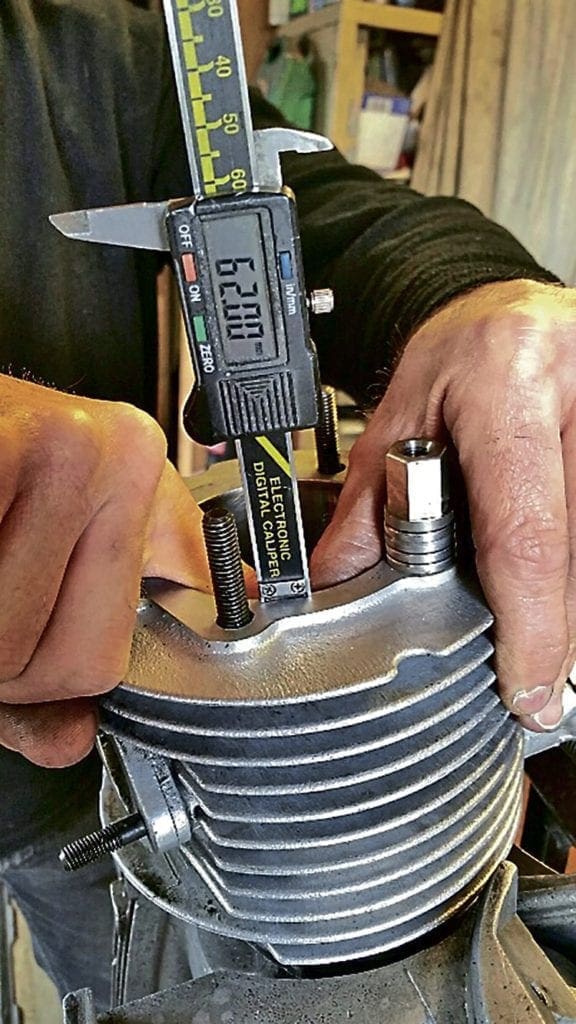
Still with cylinder in hand and using just a digital vernier with its depth gauge ground in the manner shown in the images. It is just a case of positioning it at cylinder top and measuring down to the roof of the port. The cylinder can be turned any way you wish, light added, viewed from top, bottom or through the inlet or exhaust port to get the most accurate measure. When absolutely correct, the gauge can be locked off on its thumb screw to avoid slipping and double checked ensuring the gauge is sat square to the top and flush to port roof using eyesight and feel if required. When happy, the numbers read off and converted to degrees.
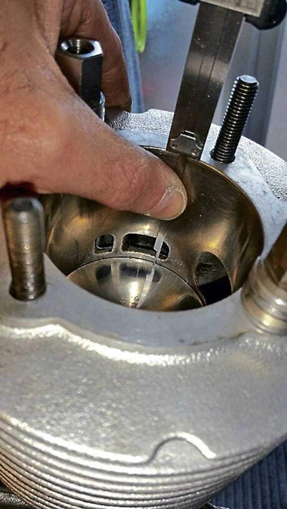
The results of this method produced port heights for exhaust as 33.45mm and for transfer 46.29mm so these give us 185.96° exhaust and 135.18° of transfer leaving us a blowdown of 25.39°.
Method comparison at a glance
Method Exhaust Transfer Slowdown
1 187 136 25.5
2 186.5 135.5 25.5
3 187.93 139.01 24.46
4 190.87 141.69 24.59
5 185.96 135.18 25.39
Differences in results and method preferences
So you can see, measuring the same cylinder using five different methods gives us the following variations: exhaust port measurement range is 185.96 lowest to 190.87 highest a difference of around 5°. Transfer port measurement range is 135.18 lowest to 141.69 highest a difference of nearly 6.5°. Having tried the various methods over the years I’ve found method 1 and 2 to be close, but is fully dependent on the eye of the person taking the measurement and the amount of chamfer added to the port. Having a good eye for this due to it being my job was the main reason for the results being fairly close so I would expect a bigger variation if done by the ‘occasional builder’. Method 3 takes longer to do, is fiddly with just one person and requires additional working out that is more complicated than it first appears. Method 4 takes the longest time to do, and for me is the worst offender as it produces a port map of the chamfers, all of which are different and produces the figures furthest away from all other methods. Method 5 is simple, it took five minutes (after taking about four hours to complete methods 1 to 4) and was by far the easiest. It does not require an engine to build on with gauges/degree discs, and the least amount of tools is required. It’s also the most accurate due to having the ability to actually see what you’re measuring. Plus, due to it being in mm, it converts to a figure in degrees (185.96) which is in hundredths of a degree, rather than a degree wheel which at best is to half a degree unless the disc is the size of floor to ceiling,
Accuracy matters
It was good to revisit the measuring methods and highlight the differences, as quite often they are quoted by cylinder manufacturers, retailers, tuners, home builders etc. but just like you would need to know if a dimension was in mm or inches, the measuring methods in this example will play a role in the result!
An example is that an exhaust designer using accurate calcs or software working on a pipe with a designed exhaust duration of 180° could have a tuner cut a cylinder using the port map method to say 188° then a home builder assemble it on his motor with a degree wheel to 185, thus resulting in a pipe designed to peak at 8500rpm… falling 400rpm short! Lost power, lost revs, lost speed.
As a tuner or developer, sticking to one method, be it the best or worst, is ideal, as long as it’s repeatable it wouldn’t matter too much if it’s intended for sole use. It’s the interaction before and after when cross reference is required when it really becomes most important.
The kart industry, and Malossi as a company example, recognise this scenario and for all their high-end engines or racing kits provide a specification handbook with every bit of data and a dimensioned port map for the builder to cross reference the dimensions, and adjust accordingly where required. Unless the set-up is built as quoted a lesser performance is achieved. Happy measuring, that’s all for this month, stay tuned.
Words & Photographs: Darrell Taylor

