MEASURING, BURETTING & CALCULATING
Building a decent engine involves a surprising amount of maths. Dull it may be, but the end results certainly are not Darrell Taylor explains how to get those top end measurements spot on…
There are a few methods of measuring the compression ratio of a two-stroke engine which I’ve found useful. The first method is on the assembled top-end of the engine and is the most accurate. With the motor built and its cylinder height set correctly (to give the desired porting specifications), and the head set correctly (to achieve its desired squish clearance), the head volume can be measured in situ, knowing that it’s going to be left unaltered from that position.
Method
Start with just the top piston ring fitted, as you don’t want the top ring seal to fail and the second to hold as that will change the volume and you will never know. Grease up the top of the bore with the piston set low then take the piston up to top dead centre and clean off the excess grease. Apply a light smear to all the gasket faces, barrel, head and any packers or gasket surfaces. Clean off the excess as we don’t want that taking up volume space which we are measuring. Tighten down with just two nuts diagonally to speed the process, as there’s a good chance it will be removed/refitted many times!
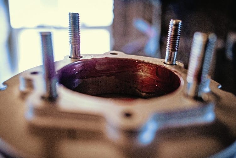
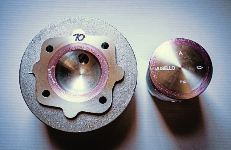
Do a squish check across the gudgeon pin axis via the plug hole, feeding 2mm solder through until it touches the bore edge and rock over TDC to crush and get a result which is even both sides. If the head isn’t pegged or rebated it’s difficult to centre so make sure the dimensions are the same or close. If you find squish is tighter one side and bigger the other, loosen the two nuts just enough to tap the head either way to obtain a good match.
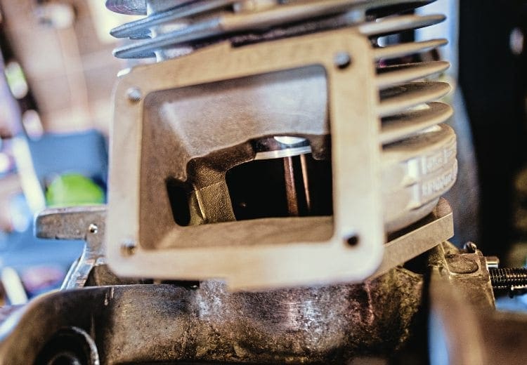
The two studs with no nuts work well as a visual guide too. Also rotate the piston back and forth just over TDC to make sure there is no contact. Depending on the build stage the flywheel might be fitted which makes turning over easy and it may have a TDC position marked up already, to help position the piston. If not, you can view the piston through the inlet or exhaust to gauge TDC or use a tool like a screwdriver through the plug hole to feel for TDC. This is a quick base setup and not too important at this stage. You may find at this point the flywheel (if fitted) magnets may pull the piston away from its TDC position, so to free your hands up wedge a piece of folded card between case and flywheel.

Next the engine needs to be set up, to sit the spark plug threaded section of the head into a plumb position, with the spark plug gasket seating area of the head level, as we will be filling with fluid to this point. The pic shows the engine rested up on the bench, set up and a spark plug extender tool used to gauge its plumb. We measure to the top of the plug thread because it’s almost impossible to accurately see the fluid level at the bottom plug thread.
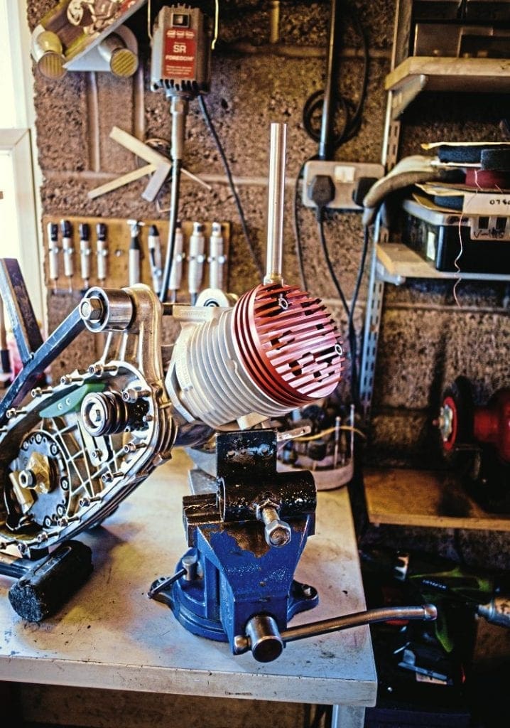
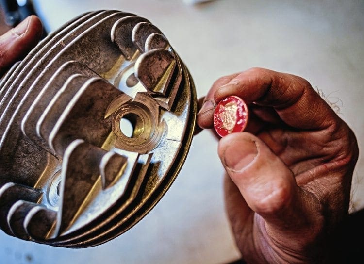
Doing it this way we measure the plug thread volume and deduct the amount from the total. The plug thread volume can be measured precisely if required although I can confidently say that all are between 2cc and 2.3cc volume for long reach plugs and 1.2 to 1.5cc on short reach plugs. A 1p coin greased on one side will sit nicely on the plug gasket head seat, as it will allow the head to be turned over and buretted-up once set to a plumb position, without falling off or being held.
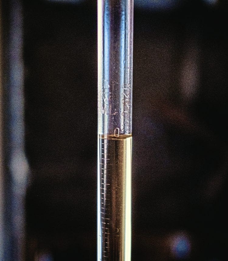
When measuring the head volume, it’s good to have an assistant hold the motor as both hands will be used for holding the burette, an engine stand or vice may be adaptable enough if not, or an arrangement of blocks or tools can be assembled to hold the motor as the pic shows. I use petrol and oil mix (petroil) as the measuring fluid which will seal better at a higher % so 5-10% is good and it’s always available in your tank to drain and use. The burette is filled with petroil to near the top then released on the tap to obtain the exact zero mark, as pictured, so is then ready to be released into the plug thread hole.
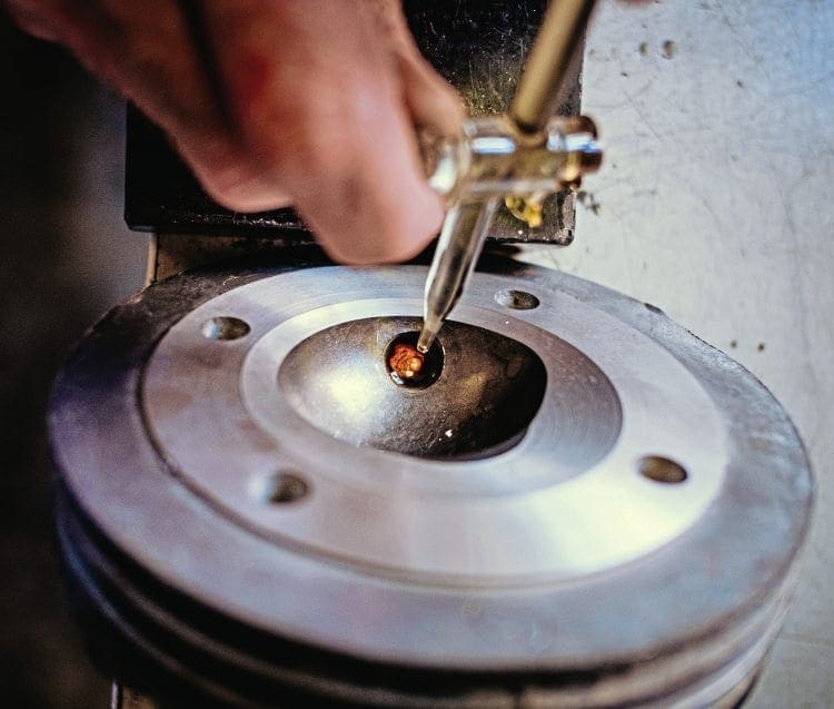
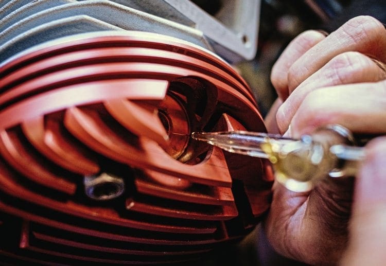
This is filled to approximately the bottom of the spark plug thread covering one or two threads up, and now we can use the fluid as an excellent measuring tool to get a very accurate TDC. This is quick to do via gently rocking the flywheel until fluid rises to its maximum and wedge the flywheel again with the card, or have your assistant hold steady, then continue to fill to the top level. While the measure is being taken be careful to watch for leaks or the level dropping as a result of the petroil breaking the grease seal. It’s worthwhile rechecking a second time to confirm the results. So now we have a volume figure to provide us with an uncorrected compression ratio, which I call a TDC figure.
Calculations
First work out the cubic capacity (CC) of your engine. I use a quick calculation of bore x bore x stroke x 0.785 = CC. So a typical 70mm bore, 58 stroke, TS1 225 is 70 x 70 x 58 x 0.785 = a cubic capacity of 223.09.
The total burette volume measured to the top of the plug thread = 27.3cc.
Total plug volume measured = 2.3cc. So deducting the plug volume leaves 25cc head volume.
To work out the uncorrected compression ratio, it’s cubic capacity + head volume head volume = compression ratio.
So 223.09 + 25 25 = 9.92.
A second method of measuring a head volume, which can be used when no motor is available, is to grease the piston to the cylinder head, these being the only two parts needed. This method is not as accurate as the squish clearance is calculated mathematically and not via burette. It’s also calculated as a parallel clearance which is often not the case and hasn’t got the cavities included in the measurement, which are present in a built up engine (like the gap at the edge of the piston down onto the top ring, or the oversize head/gasket which is bigger than the bore size and is often used e.g. 71mm gasket on a 70mm bore gives a 1mm gap all around that contains a fair bit of volume). It’s still a good method though.
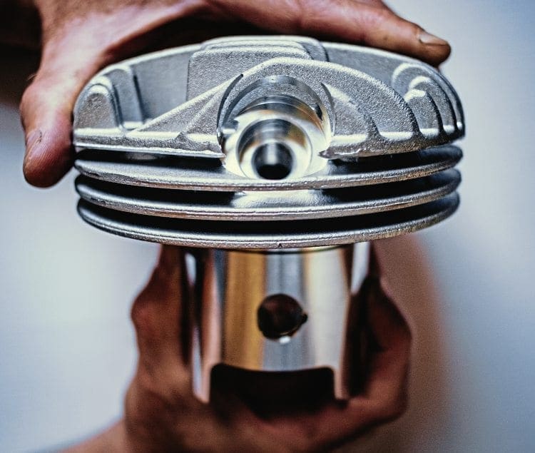
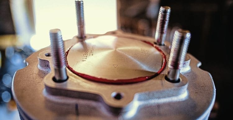
If measuring compression and volume changes are required and you know that 2cc requires removal from the bowl then this is a quick method to check the progress of the work before returning to the engine for a final measure. To measure this way apply grease to the squish band area of the head and press the piston into the grease to form a bond, then separate and clean off any only excess grease. If its centre-plug type and piston skirt is level it’s easy, just sit on the worktop and fill to top of plug thread. If its side plug then an assistant will be needed to hold it in position for you. When you have the figure, let’s say 21cc, deduct the spark plug thread volume, say 2.3cc, and it leaves us with 18.7cc. But that’s without any squish band volume. A quick way to get close on the squish volume as a working yardstick Is to use the previous calculation for cubic capacity. The last example, 70 bore x 58 stroke, was 223.09cc. If I add the required squish, say 1mm, to the stroke number 58 to make it 59, and calculate again at 70 bore x 59 stroke, the new cc is 226.94. The difference between the two is 3.85cc as our 1mm squish calculation. All other calculations remain the same.
Words & photographs: Darrell Taylor
This article was taken from the July 2016 edition of Scootering, back issues available here: www.classicmagazines.co.uk/issue/SCO/year/2016


